Wind energy for Tula/ Ethiopia 2013/2014 (Draft stand 2012)
Directory
- Alternative Energy Generation with a Future
- Experiences with the Wind-Solar-System in Ethiopia from 2005-2012
- Basic principals of the Wind-Solar-Project by “Selbshilfe Ätheopien e.V“
- The Technical Base Principal of the Wind-Solar-Plant.
- Over all view
- Wind power
- plantPhoto voltaic plant
- Generating station (transformer station)
- Cable connection to consumers
- A Wind and Solar power plant for Tula Project Plan
- Wind conditions
- The village, Tula – geographical structure
- The capacity of the Wind-Solar
- plantPower generation
- Normal consumer
- Special consumer
- Special Case, the Church
- Electricity reimbursement
- The realisation of the Project – Work Distribution
- Steps to put project into action/ Time plan in view
Attachment: List of material to be purchased in Addis Abeba 6-12 2012
1. Alternative Energy Generation with a Future
Great regions of the Ethiopian countryside have no access to electricity. The electricity production through diesel generators can be helpful in individual cases. But for a whole village it is not an acceptable option for a continual and regular energy supply. With increasing oil prices on the world market, right from the start Africa should work for an alternative option to generate its own convertible energy supply. This would be a real long term improvement with a future.
Due to the complicated geographical settlement structure of Ethiopia „Island energy systems“ offer themselves as a perfect solution. The energy is mostly generated from one central point. For example, in a village and by means of a self-sufficient electricity grid, delivered to the consumer. By using alternative energy only a minimal amount of diesel fuel would be needed for emergencies. Alternative Island energy systems of a small dimension are simple to construct and also in rough terrain, easy to install, (Low transport mass) and through local maintenance personal, easy to run. The advantage over individual Mini-Solar plants is that the grid gives an overall norm of 230 V AC-voltage (50 Hz) and therefore the universal use of electricity for standard electrical appliances is made possible.
Due to the limited Dimensions these systems have only one limiting factor: efficiency. They are designed to power lights, small tools, radios, Computers, water pumps and other small machines. These systems are not however made to power large cooling appliances, large machinery or heaters.
2. Experiences with the Wind-Solar-System in Ethiopia from 2005-2012.
The organisation “Selbsthilfe Äthiopien” (Self-help Ethiopia) has set up a self-sufficient Wind-Solar-Energy-System in the Ethiopian village Debo (near, Mertule Marjam, Gojam region). Since 2005 it gives a power supply to Public buildings such as the Health centre, school, local council offices, the monastery church, village square street lighting and the generating station workshop as well as supplying some private homes.
The energy producers in Debo are one Windmill 3.5 KWp and one solar plant 1,4 KWp. The consumers are connected by a 1 km long earth cable. The initiative group “Selbsthilfe Äthiopien e.V.” in Debo has been able to collect a great deal of experience with regard to technical solutions and the organisation of operation and maintenance. More detailed accounts to these experiences are available in English and German under
Link to Homepage Debo as well as Link to Reports of 2011 and 2012
3. Basic principals of the Wind-Solar-Project
- Because of the many years working in Debo a foundation of experiences, results and project principals have been made. These have been noted as follows.
- The basic goal is to create an energy system with the perspective of all essential parts being independently produced and used in Ethiopia, this being a particular principal for the production of the Wind energy installation, which can also be built in a workshop. The wind energy system is designed by “Self-help Ethiopia”. Therefore there are no licensing laws from private companies.
- The technology is solid, simple and is transparently built for service personnel and also uses z. T. customary production components.
- The technology concept does without complicated full automatic solutions. The system is automatic but the plant demands regular check ups that the technicians maintain a “living” connection to the system and therefore stay confident in their tasks.
- The wind energy system is easy to lay down and therefore safe to maintain.
- The constant operation of the system means that at least two part time maintenance technicians, with basic knowledge in electro technology and mechanics are needed. A timely qualification must be organised. One of the personnel should be a woman.
- The maintenance technician will have the use of a workshop with electric power, containing a complete range of machinery and tools (grinder, drill, small generator and eventually, welding equipment and fuel supplies…). This workshop can also be a service centre for the village (hairdressers, battery re-charging station and repair centre…). This workshop can also be a good place for training the young and adults in electro technical and mechanical qualifications.
- The energy plant must generate and manage its own finances well. Through the workshop and repair contracts the maintenance technician has the possibility and individual responsibility to earn money. The electricity charges to the consumer for a re-charge service can be collected as a back-up for regular maintenance costs. This is very important for the long-term prospect of maintaining a permanent power plant of this type.
- To realise a mutual responsibility it is recommended that all consumers join an Electricity cooperation. Every consumer household will pay a connecting fee to create a base capital. The reimbursement of electricity will follow (to save on expensive meters) at best with a pre-determined monthly charge.
- The management of the energy system will be organised by the Electricity committee (Technology, electricity cashbox, Inventory and accounting…)
The electricity committee will be represented by both men and women.
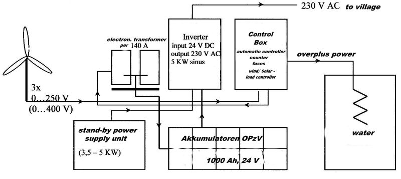
4. The Technical Base Principal of the Wind-Solar-Plant.
4.1. Over all view
4.2. Wind power plant
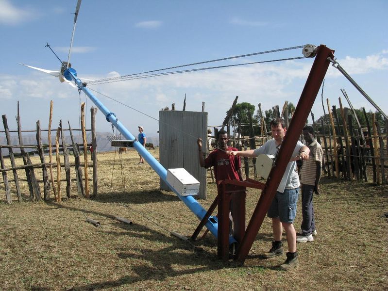
- Height: about 10 m
- Performance: 3,5/ 4 KW KWp
- Rotor: Rotor diameter: 4 m / 3 blades (Plastic)
- Generator: Synchron, 16-pole / 0… 400 V 3-phase AC / Permanent magnet.
- Electricity production already from 2 m/s Wind speed
- Performance restrictions: Helicopter mode
- Mast is easily laid down without further technicalities.
Present performance of the wind plant in relation to wind speed
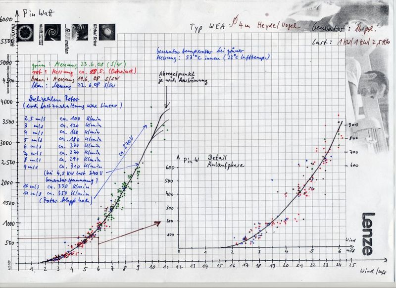
Average daily yield in relation to the average wind speed

The deciding factor is, with which daily energy levels can be reckoned with. After many years of measuring the following can be said:
The daily yield can be predicted from predominant average wind speeds. The performance is lower in the high lands because the air pressure is lower. The knowledge of the wind revenue is a deciding factor for the planning and building of the wind energy system.
4.3. Photo voltaic plant
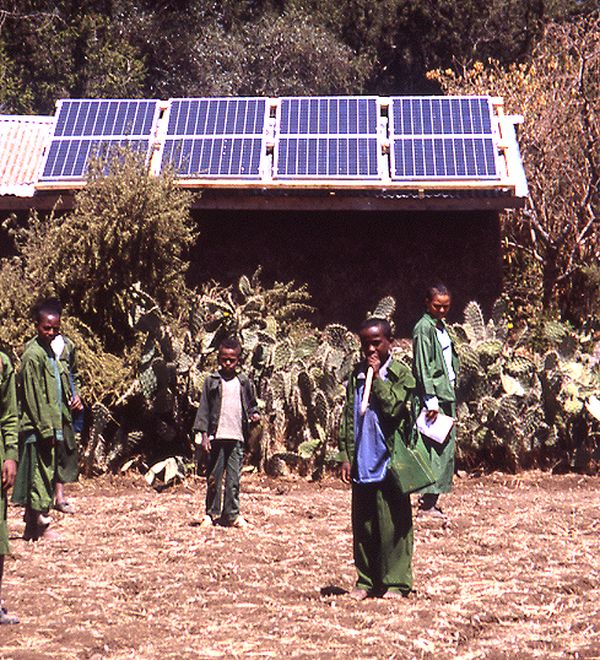
- more than 36 V DC
- approx. 2 KWp
- MPP load controller
- Installation on the roof of the transformer station
- Boards panelled parallel, in case defect or demolished boards need to be disconnected without having to shut down the whole system.
- Daily yield by sunny weather: 6-11 KWh
4.4. Transformer station
A traditional clay house approx. 3x5 m, a sloping corrugated iron roof with wooden frame work for the installation of the P.V. Panels, a lockable door, a window, inside there should be a work bench and possibility of storage of spare electrical materials/ specialized tools and measuring gadgets.
Components
- Wind load controller: prevents overload to the accumulator and diverts excess energy to heat regulators (conventional immersion coils, water barrels).
- Solar load controller
- Transformer (Wind 230 V AC to 24 V DC to batteries;conventional welding inverter)
- 12 x OPzV Accumulators (Gel; standing single cells each 2 V DC, app. 1000 Ah) – for stationary operation,durability 15-20 years, Total capacity approx. 20 KWh; German product.
- Inverter 24 V DC zu 230 V AC sine, 5 KW (10 KWp short time), An automatic trip-switch to shut off when under powered (to protect the accumulator).
- Emergency generator Diesel 4-5 KW (Manual switch or automatic)
- Signal lamp on the roof: Lights up before the emergency power option shuts in.
4. 5. Cable connection to consumers
Because of the earthing potential characteristics of the electricity (two phases), electricity will be transported over a second grade power cable, with a diameter that must be adequately dimensioned for the length of cable and power performance. Underground cable and overhead lines are possible.
Underground cable
In Debo cables were laid underground (2x 20 mm²), with an additional plastic pipe as protection. The advantage being: Security against electricity theft and destruction. The disadvantage: the installation is very complicated. Bends and curves must be completely water tight and are of cause difficult to install. When cables are damaged (something that has not happened in Debo) then the damaged spot is hard to find.
Overhead line
For longer stretches of power lines with many junctions, an overhead line is sensible. Eucalyptus tree trunks, buried deep enough into holes in the ground after being treated against insects and animals and also water proofed (negative experiences made in Debo with untreated masts) make very good masts. As a protection against electricity theft and shorting, a single wire earth return insulated cable should be used. It is possible to create water tight junctions at every necessary point with special clamps. The cables are hung on the masts by hooks or loops.
Private House Connection
Every house has a simple water proof fuse box installed outside, under the roof. The fuse box can be flapped open, it is safe to touch and can disconnect the house circuit. The strength of electricity depends on the consumers needs. For a simple house the flow would be minimal, to prevent the use of unauthorised “electricity gobblers” The house connection should be mounted outside so that the technician can be allowed to make checks.
Consumer
The less electricity needed by each individual household will enable more homes to be connected to the circuit. It has been recommended that in general each house should have 1or2 power points (one for an 11 Watt Energy saving lamp) + plug sockets for a small radio or a re-charger (Torch or mobile phone) with total performance of 30 Watt. for example.
5. A Wind and Solar power plant for Tula Project Plan
5.1. Wind conditions
The village Tula is geographically relatively well positioned for the use of wind power. The Great Rift Valley directs the wind straight to the mountain range where Tula lies.
-

-
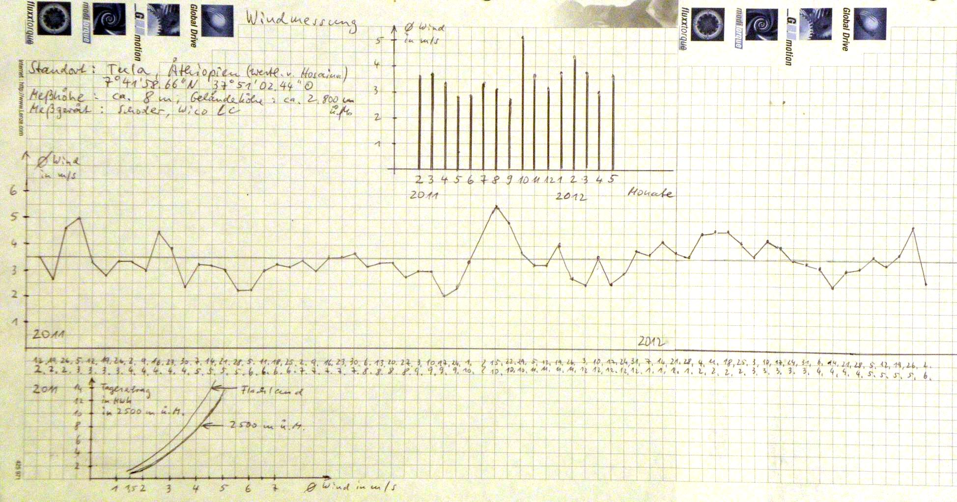
Wind power survey in Tula
The wind masurements in Tula are not yet complete. Until now measurements between February 2011 and May 2012 show for February to April between 3 and 4,5 m/s which would give a daily energy production of 5-10 KWh as a reasonable daily expectation. During June, July and August 3-3,5 m/s were measured (4-6 KWh per. day). May with 2,2-3,2 m/s is a relatively weak wind (2-4,2 KWh per. day). With an average wind speed of 4-4.5 m/s the solar plant could even be done without because the power plant would produce plenty of energy.
Tulas’ position as it is (the same as Debo) it will be necessary to combine the wind power system with a solar power plant to create extra energy to keep the system working throughout.
After the installation of the plant at Tula, weekly measurements must be taken and documented, how much energy comes from the wind power system and how much energy comes from the solar panels. This way the energy plant in Tula can make a scientific contribution towards the use of small island power plants and their performance.
5.2. The village Tula – geographical structure
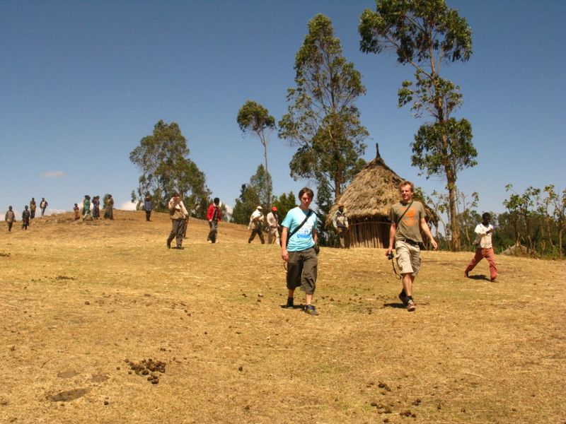
The village of Tula is a large, wide spread village with the largest concentration of houses south west of the school grounds. At the south end of the village is a free standing hill which offers itself as an ideal position for the wind power plant. This hill is easily accessible by truck, this being a great advantage. Also right next to the hill is a farm and farm buildings, which would offer a perfect base for the electro centre and a camp for the installation team. There is a water well near by. This means very short distances between the building up of the wind energy plant and the Generating station.
The wide expanse of the village creates the greatest challenge not only in the laying of the cables but also in the distribution of the electricity. The sketch shows the plan for the position of the power line cables, which should follow the path as overhead lines. Masts are plentiful in Tula and easy to make as there is an abundance of eucalyptus trees in the area. Additional cables must branch off from the main central line. The house connections will then branch off from these extensions.
Cable
- Main power line: 2x 25 (30) mm², Single wire earth return, insulated
- Extension lines: 2x approx. 4 mm², Single wire earth return, insulated
- House connection line: 2x 2,5/ 4 mm², Single wire earth return, insulated
5.3. The capacity of the Wind-Solar plant
The average amount of usable energy can only be estimated, because there have been no long-term Wind und Solar measurements made in Tula. It is usual that at the start, only a few consumers will be connected. When the energy production can start to show reserves of excess energy then the grid can be extended step by step.
More energy can be expected in the months of October to June. The main problem will be the Rain season, because in this time the solar panels (and eventually also the wind turbine) will produce less energy. In these times the emergency electricity generator will come into action to balance the power levels.
It must be noted that, through transformation and recharging approx. 25% of the generated power is lost.
Wind and solar plants make a good team, as the wind turbine can also use wind at night and the solar plant generates the power during the day.
5. 3. 1. Power generation
- Solar plant: average energy yield per day approx. 6 KWh (conservitively calculated)
- Wind energy plant: average energy yield per day 5 KWh.
- Total energy production: approx. 11 KWh per day.
- Usable energy per day minus 25% lost: approx. 8 KWh.
5.3.2. Normal consumer
Connection performance per house: 30 Watt (1-2 Energy saving lamps á 11 Watt, 1 socket for a Radio or re-charger).
Average time of use per day: approx. 2,5 hours (= 75 Wh = 0,075 KWh). In reality the consumers will use power for longer but it is seldom that the whole power supply is completely used throughout this time. With that, about 100 houses can be connected.
If 100 houses were to use the given 30 Watt, that would be 3 KW present performance. The inverter has a performance output of 5 KW.
5.3.3. Special consumer
While not all consumers will be using the grid at the same time, on average a maximum of 2KW will be used at one time. This allows the connection of Special Consumers that can use higher performance for a short space of time. That means that it is no problem to run small machines (Drills, sanding machines, hair cutters etc.), pumps, copiers, printers, projectors, and loud speakers etc. This is interesting for the school, workshop or other official buildings. As the inverter produces a pure sine-electricity (50 Hz), even sensitive equipment can be connected, such as computers.
Recommended performance connection
For the test run of the complete system it is recommended that at first only 70-80 houses are connected. When it can be seen that there is excess energy then the grid can be extended to 100 houses or more.
5.3.4. Special Case, the Churches
There are three churches in Tula. Each of these churches should have an equal supply of electricity. The time of use of electricity in the church is limited to a few hours. Laying the extensive lines of cable is very expensive. Therefore, it must be thought about, whether each church should have the availability of their own individual emergency generator. For example, the cable cost from the school grounds to Luther Church (830 m) One could obtain three emergency power generators with much reserve fuel. The advantage being, that a considerable higher performance can be made available to the churches.
5.4. Electricity reimbursement
The amount of the monthly electricity charges must be handled by the Electricity Co-operative. They should not how ever be less than 15 Bir per month. With 100 consumers the monthly income would be 1500 Bir, per year 18.000 Bir. From this the cost of diesel or small repairs can easily be covered.
6. The realisation of the Project – Work Distribution
The realisation is only possible with the cooperation between Mekane Yesus / EECMY DASSC and the organisation „Selbsthilfe Äthiopien e. V.“.
As the members of the organisation „Selbsthilfe Äthiopien e. V.“ are carrying out this work on a voluntary basis (on their holiday), the realisation of this project must be carried out with the following work distribution:
While „Selbsthilfe Äthiopien e. V.“ can obtain and install the power plant (Solar, Wind, E-Station) as well as giving instructions and a limited financial aid for the project.
EECMY DASSC will be responsible for the organisation. (Financial applications, technical training, organisation of material import, decision as to which houses will be connected to the grid, through meetings with the community, organisation of the laying of the cables for the village and the education of the Electricity Co-operation). With this cooperation the realisation of this project will be possible.
6.1. Steps to put project into action/ Time plan in view
6-12 2012: Preparations
- Presentation „Selbsthilfe Äthiopien e. V.“ with EECMY DASSC; Financial plan, Explanation of import procedure, clarification of the work distribution …
- Building of the Mast construction in Addis Abeba (technical, drawings)
- Vote to be made for three technicians in Tula (min. 1 woman)
- Purchase of materials, Tools and machinery in Addis (See att. list 1)
1/2 2013: 1st Building project in Tula by „Selbsthilfe Äthiopien e. V. and local technicians
A material import from Germany at this point in the construction is not necessary (Tools and small parts in rucksacks); more important material and machinery must be obtained before this date, in Addis (see list attached).
- Camp/ workshop/ store (near to the farm yard?)
- Foundation of the wind turbine and earth anchoring (total approx. 2-3 m³ concrete)
- Lying of earth cable and earthing band from the wind turbine to the E-Station (approx. 50 m)
- Planning of the position and foundation of the E-Station (small house, approx. 3x5 m, corrugated iron roof.)
- Laying of a short test cable stretch (max. 100 m main cable, branch line and house connection) as an example for the further work to be done by the technicians.
- Clarification of the planned power lines through the village. (See att. Aerial photos)
- Pre-thoughts with Mekane Jesus about the set up of an Electricity Co-operative
- Clarification: to which village areas must the electricity grid stay contained (reasonable and expected cable length)?
- Clarification of the Technicians training
3-9 2013: Technicians Training in Hosseina
- Education of theElectricity co-operative in Tula
- Purchase of electric cable in Addis Abeba
3-9 2013: Purchase and putting together of components in Germany
- Wind turbine components
- Solar components
- Elektronic/ Electro technic
- Akkumulator
- Mast hitch, with equipment
- Installation material (Energy saving light bulbs; house connection fuse boxes; connecting parts, switches …)
- Workshop equipment
- Transport of the components to Addis Abeba (Container, by ship?)
9-12 2013: 2nd Building project in Tula: Building of the E-House (transformer station) and laying the of the village cable in Tula through the own responsibility of the technicians.
- Completion of the E-House (incl. Roof frame for solar panelling)
- The laying of the main cable to the school
- Laying of the extension cables to the house group
- Connection to individual houses (to start max. 70-80).
1-2 2014: 3rd Building project in Tula: Erection of the complete system in Tula (Total 27 days)
- Erection of the wind turbine
- Fitting of the E-House (Accumulators, E-components, Emergency power generator)
- Solar installation
- Fitting of the workshop in the village
- Installation of some test street lamps
- Starting up of the power plant
- Installation of the emergency machinery in the church
- Instructions for the technicians (Performance measurements and wind measurements)
- Clarification with Mekane Yesus: Tasks of the Electricity co-operative
- Tasks for the technicians, Service plans, measurement protocol
6.2. Running of the Power Plant and Performance Measurements
The technicians as well as the Electricity co-operative must collect experience with the power plant. It would be good if there would be one person responsible at the farm buildings, next to the power plant who was trained in:
- Reading the metres
- Drawing up the measurement results
- Starting up the emergency electric generators
The documentation of generated and used energy levels is very important, that the whole system can be scientifically evaluated. This is in the interest of the perspective of the further development of the project.